


Hello again,
My love for electronics was not new but the one from early teens. Fascination with blinking led lights, making a mic amplifier and so on.
Life as in many stories got busy with study and job. After completing my design graduation I started working as a professional graphics and presentation designer. Nine years of jobs brought me to my glass ceiling and with a bump of confidence from wife, I finally jumped into full time freelancing in 2015 – (Top Rated Plus designer – top 3% among 18 million freelancers)
Thankfully freelancing also came with a bit of freedom to work on personal projects, be it writing these blog posts or teaching grad students at IQRA university.
Drum roll for Digital thermometer
For my office space, I wanted to have a digital thermometer, that can display both temperature and humidity of room. After a bit of research on internet, Arduino platform came into the bright sun. It is no doubt the best thing for beginners like me. After watching some tutorials, it felt like a doable task, even for me with no background in programming.
Where’s the fun in buying
The DIY – do it yourself is not always about money saving (though in most cases you can). It is about the satisfaction of doing things by your own hands. Thus my aim was to make my own circuit.
Edit 2: I learned that median filter is better than running average filter because median filter takes the center reading, thus less affected by the peaks of noise than running average.
Disclaimer: Let me warn you that these are finding of the real world that I found may differ from simulations or online schematics/tutorials. I may be wrong in assuming some results, but those are my findings and I intend to keep learning. All the things I did are available in the shape of good tutorials on Instructables or youtube, I just merged them as per my taste. I aim to just share my experience, so do some research and you are responsible for each of your actions.
Purpose:
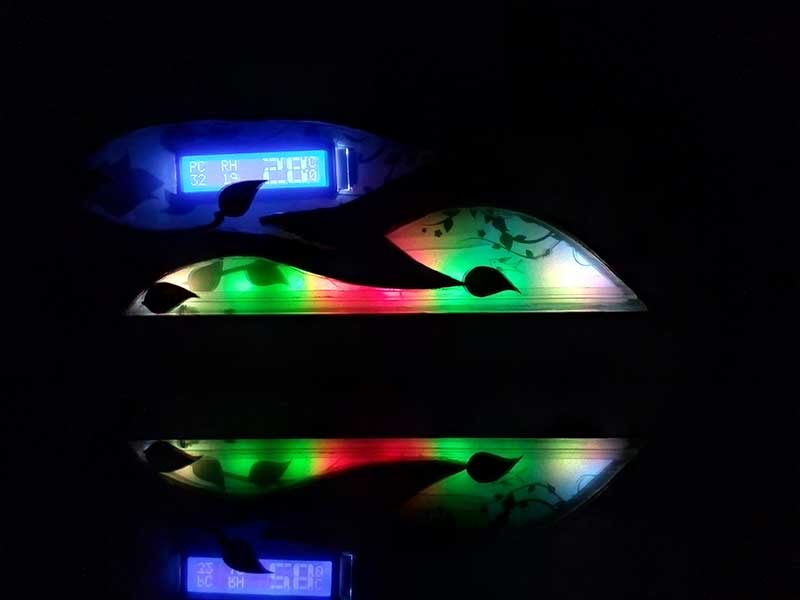
Sparrow will be assisting me in
- monitoring my PC temperature and display it on lcd (northbridge chip temperature to be exact)
- after an adjustable interval, PC case fans run at an adjustable speed
- if PC is hot above the adjustable limit – fan runs at an adjustable speed
- Room Ambient Temperature and display on LCD
- Ambient Light sensor (10W led turns on in dark)
- Dancing LEDs
Purpose of this post:
Learned a few things from a newcomer’s perspective, so want to share it and may save other people from going through the same frustration.
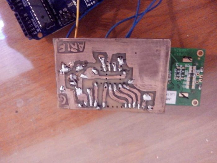
I used mix of PCB and veroboards as per ease and availability. Wiring 16 RGB leds (RBG leds in my case) would be quite messy as there would be 48 wires if done with point to point. So PCB was way to go. Used the toner transfer method (google it).
I have also attached pcb pdf (commented for ease) for leds wirring part.
All the LEDs are powered via 3 dedicated Shift register ICs 74HC595
PROBLEM FACED HERE:
Since I am new to this side, I didn’t took into consideration the max current 74HC595 can output i.e. 56ish milliamp. I used the common 220 Ohms resistors used everywhere on internet, here are the current drawn by leds:
Red leds : 12.5 ma X 16 = 200 ma ( 3 times the limit)
Green and Blue: 7.5 ma x 16 = 120ma ( 2 times the limit)
this mean that i cannot drive all leds at one, even if i decide to live on the edge and IC’s life would be very limited (if at all).
SOLUTION:
Upon realization that I am way above current limit, I had to replace the 220 Ohms with 1K ohms for Green / Blue and 1.2K for Red leds. The light were a bit less bright, but still plenty of light and everything in optimal range.
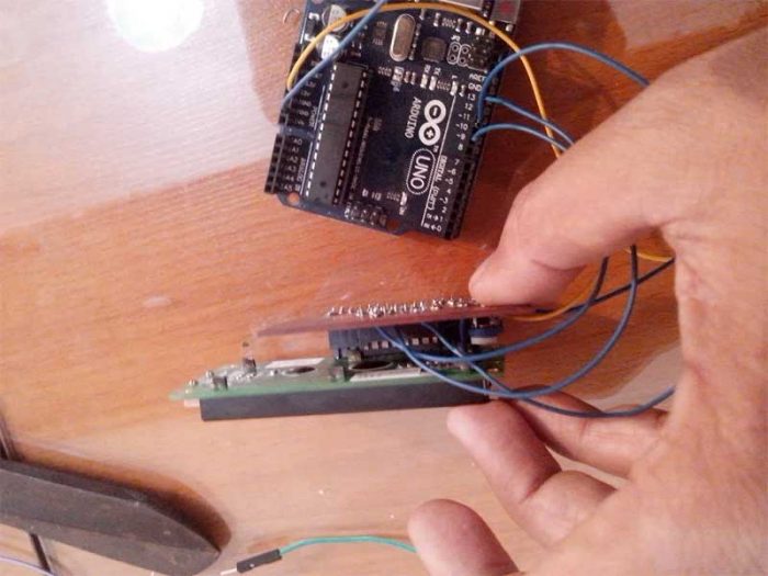
Step 4: Input and Sensors
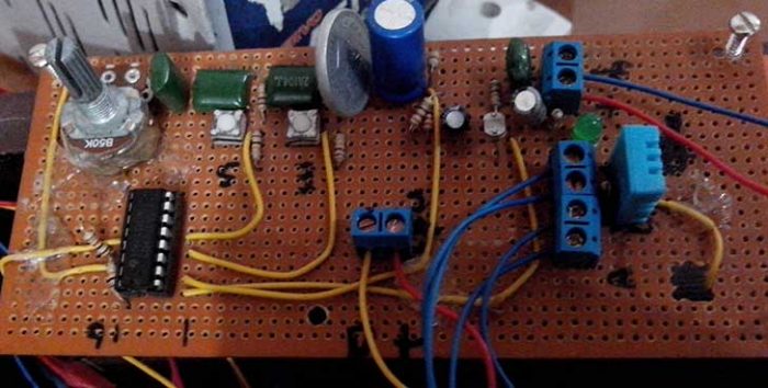
Input board comprised of :
- an analoge multiplexer CD4051, (this is used with arduino to add more input pins).
- 2 x LM35 sensors (room temperature and PC case temperature)
- DHT11 – humidity and temperature sensor
- 2 x buttons for changing settings
- 1 x potentiometer for changing settings
Problems
Dust is a major problem in my are specially in this time of year – I covered all fan ducts with a fine cloth so now it fine dust that comes in 😀
Switches can bounce (google switch bouncing) and lm35 can pick up noise.
1- To resolve the matter I have used software and hardware solution. Hardware solutions are the green capacitors 104J for debouncing and large capacitor near LM35 supply line for filter any noise that may be in power supply line.
Quick info i found:
http://www.lh-electric.net/tutorials/gnd_loop.html… for deeper understanding read :
http://www.analog.com/library/analogDialogue/archi…
2 – Also used star grounding technique to avoid any ground loops.
3 – Used shield wire and snubber with PC sensor due to longer wire (also mentioned in LM35 data sheet – google it)
Step 5: Casing
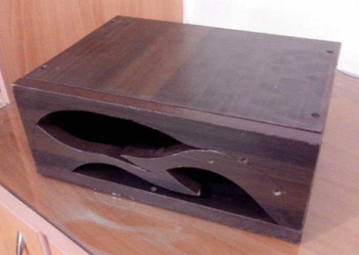
– Casing was made out of laminated Lasani wood sheet (MDF). Had a jigsaw cutter so tried to made it a fancy box to match the name of sparrow. (not yet good at wood work but definitely going to improve my skills)
– For the foots of case, I simply cut the silicon tube and screwed it to bottom.
– For front panels I used cheap plastic container and with paper cutter cut it as per openings.
Additionally:
I have also pasted aluminum sheet to the base of case and grounded it to reduce chances of wires picking up interference from atmosphere. To eliminate the chances of things shorted i paste cardboard over it so its non conductive.
Step 6: Reducing LCD Pins
By default LCDs used 6 pins on arduino and that’s a lot for small arduino. I googled and found some good tutorials, but this worked for me, now only 3 wires instead of 6, YAAY! SAVINGS :
http://rowansimms.com/article.php/lcd-hookup-in-se…
(Above tutorial used some modified LCD library. It was hard to find library link, I had to google a bit, I am attaching the LCD Library which worked with above tutorial only for the sake for ease of new comers, All rights are reserved as per original creators. Let me know if i am breaking any copyrights, I will comply )
Not much problem here but the funny thing that i made PCB without mirroring the design, and pins are not opposite. now i had 2 options , redo the pcb or I flipped the IC legs 😛 (i.e. the printed side of ic is downside now) haha.
Step 7: Coding
As i mentioned at start that I am designer by profession, so coding was something alien to me, but thanks to tons of tutorials examples and code out there i made my way through it and compiled 8500 words of code for the project. That was plenty of things and management in Arduino Sketch software was not enough, i returned to word made tables for each section and color coded them. This made browsing through sections easier.
I used headline with several styles to mark main function and sub functions.
For PWM functions I used Shift PWM (software pwm from http://www.elcojacobs.com/shiftpwm/ ) Thanks to him for hardwork.
For Long / Short press of buttons, I used this great tutorial.Thanks to author for effort :
https://www.instructables.com/id/Arduino-Dual-Function-Button-Long-PressShort-Press/