


Hello again, this is part of my second arduino based project, I think I dived quite deep with first one, so many thing look easier now. So lets make a DIY Vibration Sensor
Edit: 2022: wow its been six years, and I am happy to report that it still works perfectly!
Edit: 10 Mar 2016: Found some tips for circuit to work better – Must check last part.
There are plenty of good and low cost vibration sensor on market, like this good looking https://www.adafruit.com/products/1766

Problem is shipping costs are too much here and local vendors tends to sell 4x expensive (if they willing to understand what you require). So looking at schematics and images and the restless soul of mine I decided to make my own sensor.

This sensor is going to be used in larger project, I am making for my son. I am successful in my test so I am sharing the knowledge, may it help someone else with creative DIY itch.
This is inspired from this instructable, but mine is more of a poor man approach (i.e. things readily available)
Things Required
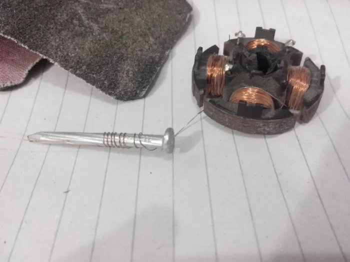
– I used coated copper wire out old pc cooling fan, (can be found in various old things lying around).
– 220 ohm Resistor
Making the sensor
1. Process is very easy. First rub the coated wire with sandpaper to make sure wire is clean and electricity can pass when it touches other pole.

2. Wound the cleaned copper wire on nail as per you desired length, you can take out and shake to check the bounce of spring, when thing are as per your taste, cut the extra wire.
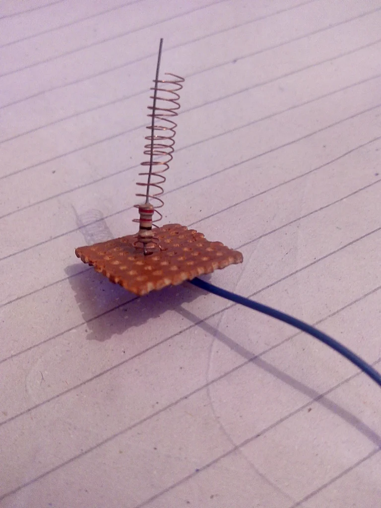
3. solder the 220 ohm resistor to veroboard, as shown in picture, this way it will not only be a bit stable joint but also protect pins from too much current in case of accident. The resistor leg is touching the spring in pictures, that’s because it is very sensitive and the board needs to be vertically straight (that’s the sensitivity I was looking for). You can use thicker wire or real spring, depending what you need it for and how much sensitive you want it to be.
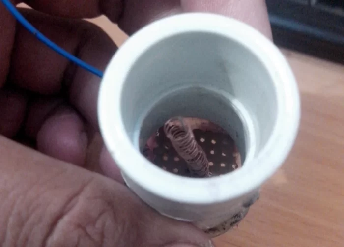
You can close the setup in a piece of PVC pipe
Lets test it with Arduino.

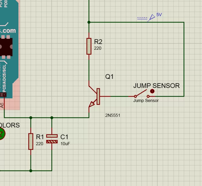
Lets attach it with Arduino as show in above diagram). Here sensor is simply acting like a switch that turns on when vibrates. The CAPACITOR is necessary as it stables output, I guess the contact time is low for Arduino to detect and I was experiencing not desired results. So what i think capacitor does is, on slight contact transistor amplifies the signal and capacitor stores energy to give a bit stable input to Arduino.
Upon starting it Arduino will digital Read sensor, time to time. Digital read means, either its going to be ON or OFF (i.e. 0 or 1). One means the sensors contacts touched due to vibration, with following sketch the led on pin 13 of Arduino will light up for 2 seconds.
Arduino code with Digital pin
// Disclaimer, author takes no responsibility, what so ever, be a grownup, and always double check your wiring and schematic. Use of common sense can save you from many problems. Never take safety lightly.

int sensor = A5; // sensor pin
int led = 13; // default led on arduino

void setup() {

pinMode (sensor, INPUT);

pinMode (led, OUTPUT);

Serial.begin(9600);

}

void loop() {

int voltage = digitalRead(sensor); // read sensor here

Serial.println (voltage); // print voltage to serial monitor on pc

delay (1000);

if (voltage >= 1) { // if spring contacts on shaking

digitalWrite (led, HIGH); // turn on led to show that vibration is sensed

delay (2000);

digitalWrite (led, LOW); // turn off led now

} // end if voltage

} // end loop
More Sensitive Vibration Sensor
Additional Edit: 11 March 2016
have tested that we can also use analogRead to get results in floating points. This was you can set sensitivity inside program too.
Previous code read sensor with digitalRead, where it can be only 1 and 0. If we analogeRead the sensor we can have very sensitive sensor. I have tested both and they both works satisfactory. Only difference in of preference and desired sensitivity.
// Disclaimer, author takes no responsibility, what so ever, be a grownup, and always double check your wiring and schematic. Use of common sense can save you from many problems. Never take safety lightly.


int sensor = A5;
int led = A0;

void setup() {

pinMode (sensor, INPUT);

pinMode (led, OUTPUT); Serial.begin(9600); }

void loop() {

int sensorValue = analogRead(sensor);

float voltage = sensorValue * (5.0 / 1023.0);

Serial.println (voltage); delay (200);

if (voltage >= 0.5) { // set sensitivity here, increase voltage 0.5 for less sensitive , decrease for more sensitive

digitalWrite (led, HIGH);

delay (2000);

digitalWrite (led, LOW); }

}